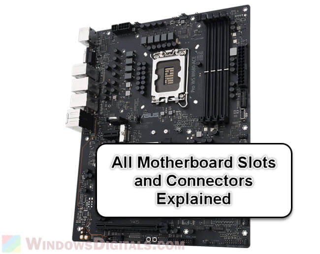
The motherboard is the main part of a computer. It connects basically all the parts and things you plug into the computer. If you’re building a new computer, upgrading some parts of your old one, or just want to know how computers generally work, it’s good to know about the different slots on a motherboard because each one has its own role. They affect how the computer works and how you can make it better.
In this guide, we’ll look at each slot on a motherboard and explain what it does.
Page Contents
CPU socket
The first and most important slot on a motherboard is the CPU socket. This slot is made just for the computer’s central processing unit (CPU), the brain of the computer. The type of CPU socket on a motherboard decides which processors it can support.
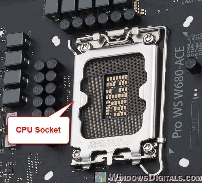
There are different socket types, like Intel’s LGA series (for example, LGA 1151, LGA 1200) and AMD’s AM series (for example, AM4). It’s very important to match the motherboard’s socket type with the right CPU model to make sure it works right.
The CPU socket is not just a place to put the CPU; it also makes the electrical connections between the processor and the motherboard. This lets the CPU talk to other parts. The way this slot is made makes sure the CPU fits just right and stays safe, which is really important for the computer to work well and be stable.
Also see: What Are The Different Types of PC Cases?
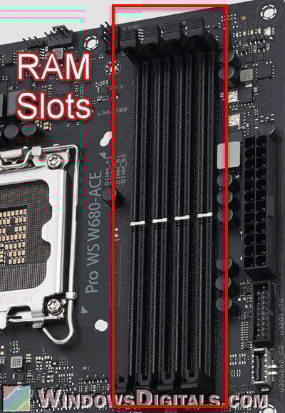
RAM slots
Next up are the RAM (Random Access Memory) slots, which are really important for the computer’s memory system. You put the RAM modules in these slots, which are usually close to the CPU socket. Motherboards can have different numbers of RAM slots, usually between two and eight.
Pro tip: Checking Motherboard Max RAM Speed (MHz) & Capacity
Below are the main things you should know about the RAM slots:
- Motherboards support certain types of RAM, like DDR4 or DDR5. The slots are made to fit only the supported type, making sure everything works well together.
- Each slot can hold a certain amount of memory. For example, a motherboard might let you use up to 32GB in each slot. This decides how much RAM the computer can use.
- Many motherboards let you use two RAM sticks at the same time to get better performance. For this, you need to put pairs of the same RAM modules in specific slots, which are often marked by different colors to make it easy to spot.
Linked issue: 16GB RAM Installed Only 8GB Usable in Windows 11
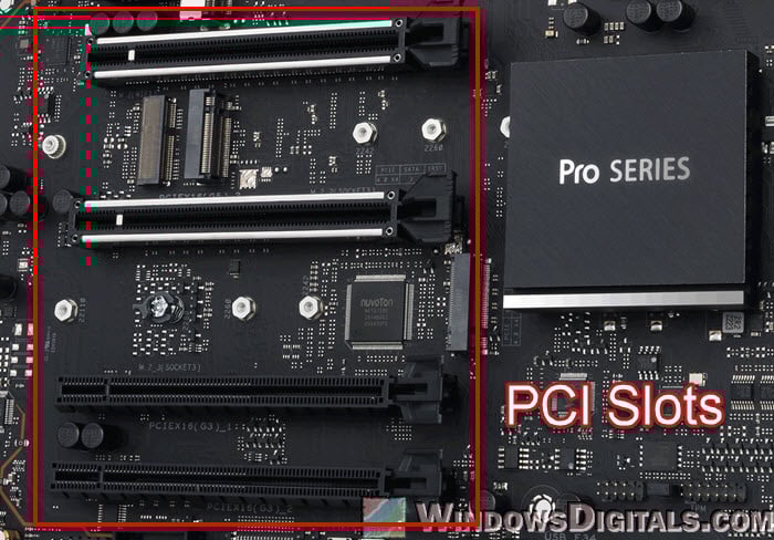
PCIe expansion slots
The PCIe (Peripheral Component Interconnect Express) slots are important for adding more things (like graphics card) to your computer. These slots come in different sizes and numbers on different motherboards and let you add various cards.
The following is a closer look at what they actually do:
- PCIe slots come in sizes like x1, x4, x8, and x16. The number tells you how many data lanes they have. The x16 slots are the biggest and most used for graphics cards because they can move data the fastest. The smaller slots like x1 and x4 are usually for other cards like sound cards, network cards, or extra USB ports.
- There are different versions of PCIe slots, like PCIe 3.0 or PCIe 4.0. The newer versions can move data faster. Even though different versions work together, using a card in a slot that’s an older version than the card can make it not work as well.
- These slots are mostly used for graphics cards (GPU), especially in computers for gaming or work that needs a lot of graphics power. They are also important for adding other parts that make the computer connect better or process things faster. Some motherboards let you use more than one graphics card, but this setup needs special settings and enough power.
Knowing about the different types and abilities of PCIe slots is really important if you want to upgrade or build a PC. They decide what kind of cards you can add, which changes how well the system works and what it can do.
Related resource: All SSD Connectors Types Explained (SATA, M.2, NVMe, etc.)
SATA and M.2 slots
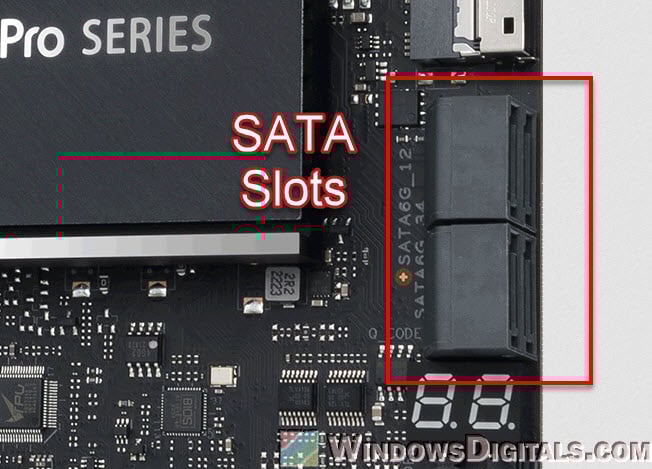
When it comes to storage, SATA (Serial Advanced Technology Attachment) and M.2 slots on a motherboard are both important for connecting storage devices like hard drives (HDDs) and solid-state drives (SSDs).
- SATA slots connect HDDs and SSDs using SATA cables. The usual SATA III slot can move data up to 6 Gbps. Most motherboards have several SATA slots, so you can connect a few storage devices. It’s good to know where these slots are because sometimes they can be blocked by bigger graphics cards.
- The M.2 slot is newer and lets you connect SSDs directly to the motherboard without needing cables. M.2 SSDs are small, like chips, and they go right into the slot on the motherboard. They are faster, especially the NVMe (Non-Volatile Memory Express) M.2 SSDs, which are much faster than regular SATA SSDs. They are great for the main drive where the system starts or for programs that need to get to data quickly.
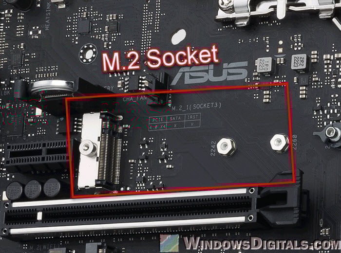
- When using M.2 slots, check the motherboard manual for details because some M.2 slots might use the same pathway as SATA slots, turning them off when used. Also, M.2 SSDs come in different sizes, so make sure the SSD size matches the motherboard slot.
Learn more: Checking SSD Compatibility with Your Motherboard
Knowing what kind of storage connector you can use on your motherboard is very important when you decide what type of SSD or HDD you want to buy. They generally decide what type of storage you can use, how many and how fast they are.
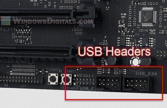
USB headers and audio connectors
Motherboards also have USB headers and audio connectors for plugging in more stuff and getting sound.
- USB headers let you add more USB ports by connecting to the motherboard. They’re used for the USB ports on the front of the computer or for adding more on the back. They come in different versions like USB 2.0, 3.0, and even USB-C.
- Audio connectors are for plugging in your headphones or speakers. You’ve got internal ones for the front of the computer and external ones on the back. They support different audio setups, from simple to surround sound.
Power connectors
Power connectors are the most important part that is responsible for giving power to the motherboard and its parts. The main power connectors include:
- 24-Pin main power connector: This is the main power link between the motherboard and the power supply unit (PSU). It’s very important for giving the power the motherboard needs to work. The connector fits in only one way.
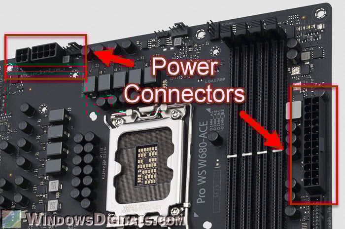
- 8-Pin CPU power connector: This is near the CPU socket and gives power just to the CPU. Some powerful motherboards have an extra 4-pin or 8-pin connector to give more power for things like overclocking.
- Other power connectors: On some fancy or gaming motherboards, you might see extra power connectors, like a 6-pin or 4-pin connector, to give more stable power for the PCIe slots or other parts. These are particularly useful for systems with several graphics cards or other parts that need a lot of power.
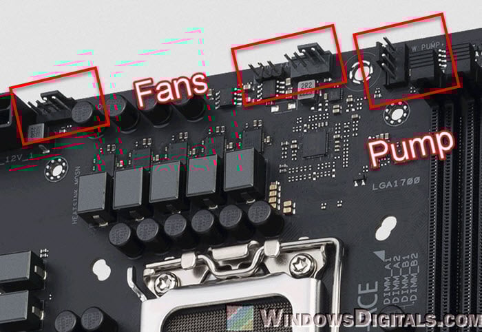
Fan headers
Fan headers on a motherboard are important for connecting and managing the fans that cool the computer. These headers do the following things:
- The CPU fan header is for the fan that cools the CPU. This keeps the CPU’s temperature under control. System fan headers are for case fans that move air around inside the computer case.
- Modern motherboards have PWM (Pulse Width Modulation) fan headers that let you control the speed of fans very precisely. PWM fans can change speed based on how hot the system is, which helps cool it down efficiently. Some headers also work with DC-controlled fans, but they don’t let you control the speed as precisely as PWM.
- You can check how fast the fans are spinning and how hot things are through the motherboard’s BIOS or software. You can also set how you want the fans to run to balance how well they cool things down with how loud they are.
Related concern: Why Are My PC Case Fans Not Spinning?
Front panel connectors
Front panel connectors are small pin connectors on the motherboard, essential for linking various functions of the computer case to the motherboard.
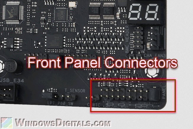
These connectors usually include:
- Power and reset button connectors: These let the computer’s power and reset buttons on the case talk to the motherboard. When you press the power button on the case, it sends a signal through these connectors to the motherboard to either start or reset the computer.
- Power and hard drive activity LEDs: These link the small LED lights on the computer case to the motherboard. The power LED shows when the computer is on, and the hard drive LED blinks or lights up when the hard drive is being used.
- Speaker connector: Some motherboards have a connector for a small internal speaker that makes beep sounds. These beeps can help figure out hardware problems during the boot process.
CMOS clear and BIOS flashback buttons
Some motherboards have special buttons or jumpers for managing and fixing the BIOS (Basic Input/Output System).
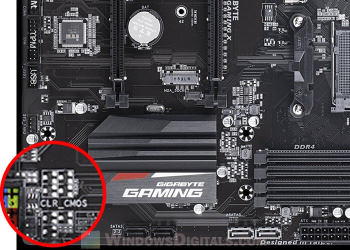
- The CMOS (Complementary Metal-Oxide-Semiconductor) keeps the BIOS settings and system time. Clearing the CMOS resets the BIOS settings to the factory settings, which is helpful for fixing hardware problems or getting back from wrong settings that stop the system from starting. Some motherboards have a special button for this, while others use a jumper that you need to move temporarily to clear the CMOS.
- The BIOS flashback button generally lets users update the motherboard’s BIOS without needing a CPU, RAM, or GPU installed. It’s especially useful for updating the BIOS to support a newer CPU or getting back from a messed up BIOS. You usually do this by putting a BIOS file on a USB drive, putting it in a special USB port on the motherboard, and pressing the BIOS Flashback button.
See also: How to Clear CMOS without Removing Battery or Jumper Cap
Debug LEDs or displays
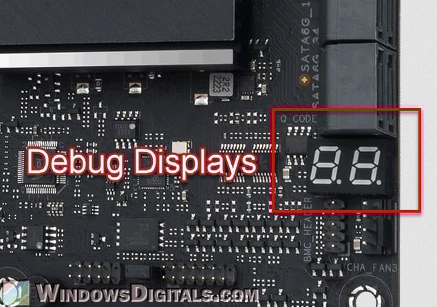
High-end motherboards often have built-in debug LEDs or displays, which are really useful for finding and fixing hardware problems.
- Debug LEDs are small LEDs on the motherboard, each one for a different part or step of the starting process (like CPU, RAM, GPU, and boot device). During startup, these LEDs light up briefly as the system checks each part. If there’s a problem stopping the computer from starting, the LED for that part stays on or blinks, showing where the problem is.
- Debug Displays are generally more detailed than LEDs. They are small digital screens that show letters and numbers. These numbers match specific steps of the starting process or particular errors. By looking in the motherboard manual, you can find out what these numbers mean and figure out what’s wrong.
One last thing
Knowing about these parts is not just for people building a new PC or making their old one better, but also for anyone interested in how computers work. With this information, you can make better choices about hardware (which can often save you money), fix problems more effectively, and be able to use all the abilities of your motherboard.